
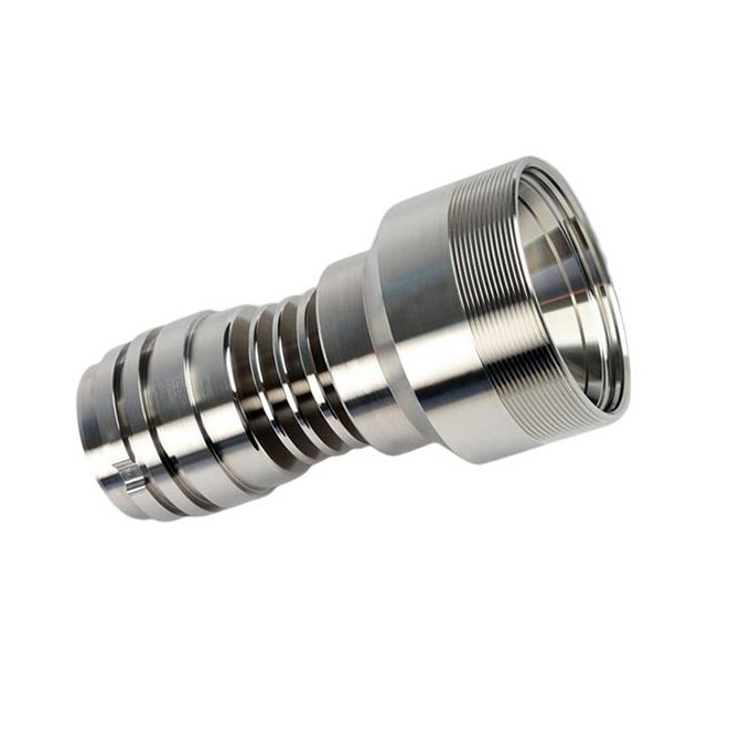
What are the shaft parts? What should be paid attention to when machining shaft parts?
what is an axis?
A shaft is basically the rotating part of any machine with a circular cross-section that is used to transmit power from one part to another or from a power generator to a power absorber. In order to transmit power, one end of the shaft is connected to the power source, and the other end is connected to the machine. Shafts can be solid or hollow as required, with hollow shafts helping to reduce weight and providing advantages.
type of shaft
1. Drive shaft
These shafts are stepped shafts used to transfer power between one source to another machine that absorbs power. Mounted on stepped parts of shaft gears, hubs or pulleys to transmit motion. Examples: overhead shafts, spools, layshafts and all factory shafts.
2. Mechanical axis
These shafts are located inside the assembly and are an integral part of the machine. Example: The crankshaft in a car engine is the machine shaft.
3. Axle axle
These shafts support rotating elements, such as wheels, which can be mounted in housings with bearings, but the shafts are non-rotating elements. These are mainly used in vehicles. Example: Axles in a car.
4. Spindle axis
These are the rotating parts of the machine; it houses the tools or workspace. They are stub shafts, used in machines, they are stub shafts for machines. Example: Spindle in a lathe.
Some details to pay attention to when machining shaft parts
1. Basic processing route of shaft parts
The main machining surfaces of shaft parts are the outer circular surface and the common special-shaped surface, so the most suitable machining method should be selected for various accuracy grades and surface roughness requirements. Its basic processing routes can be summarized into four.
The first is the processing route from rough turning to semi-finishing, and then to fine turning, which is also the most important process route selected for the outer circle machining of shaft parts of commonly used materials; the second is from rough turning to semi-finishing. Then go to rough grinding, and finally adopt the processing route of fine grinding. For parts with high requirements on ferrous materials and precision, small surface roughness requirements and need to be hardened, this processing route is the best choice, because grinding is the best choice. It is the most ideal follow-up processing procedure; the third route is from rough turning to semi-finishing turning, then finishing turning and diamond turning. This processing route is specially used to process non-ferrous metal materials, because non-ferrous metals have low hardness and are easy to block. For the gap between sand grains, it is usually not easy to obtain the required surface roughness by grinding, and the finishing and diamond turning processes must be used; the last processing route is from rough turning to semi-finishing, and then to rough grinding and fine grinding. , and finally carry out finishing processing. This route is a processing route that is often used for parts that have been hardened for ferrous materials, require high precision, and require low surface roughness values.
2. Preprocessing of shaft parts
Before turning the outer circle of shaft parts, some preparation processes must be carried out, which is the pre-machining process of shaft parts. The most important preparation step is alignment. Because the workpiece blank is often bent and deformed during the manufacturing, transportation and storage process. In order to ensure reliable clamping and even distribution of machining allowances, straightening is carried out by various presses or straightening machines in the cold state.
3. Positioning benchmark for shaft parts processing
First, the center hole of the workpiece is used as the positioning reference for processing. In the processing of shaft parts, the coaxiality of each outer circular surface, tapered hole and thread surface, and the perpendicularity of the end face to the rotation axis are all important manifestations of positional accuracy. These surfaces are generally designed based on the center line of the shaft, and are positioned with the center hole, which conforms to the principle of datum coincidence. The center hole is not only the positioning benchmark for turning, but also the positioning benchmark and inspection benchmark for other processing procedures, which conforms to the principle of benchmark unity. When two center holes are used for positioning, multiple outer circles and end faces can be machined to the maximum extent in one clamping.
The second is the outer circle and the center hole as the positioning reference for processing. This method effectively overcomes the disadvantage of poor positioning rigidity of the center hole, especially when processing heavier workpieces, the positioning of the center hole will cause unstable clamping and the cutting amount should not be too large. There is no need to worry about this problem by using the outer circle and the center hole as the positioning reference. During rough machining, the method of using the outer surface of the shaft and a central hole as the positioning reference can withstand a large cutting moment during processing, and is the most common positioning method for shaft parts.
The third is to use the two outer circular surfaces as the positioning reference for processing. When machining the inner hole of the hollow shaft, the center hole cannot be used as the positioning reference, so the two outer surfaces of the shaft should be used as the positioning reference. When machining the spindle of a machine tool, the two support journals are often used as the positioning datum, which can effectively ensure the coaxiality of the taper hole relative to the support journal, and eliminate the error caused by the misalignment of the datum. Finally, the taper plug with the center hole is used as the positioning reference for processing. This method is most commonly used in the machining of the outer surface of the hollow shaft.
4. Clamping of shaft parts
The processing of the taper plug and taper sleeve mandrel must have high machining accuracy. The center hole is not only the positioning reference for its own manufacture, but also the benchmark for the outer circle finishing of the hollow shaft. It is necessary to ensure that the taper plug or taper sleeve mandrel is on the taper surface. It has a high degree of coaxiality with the central hole. Therefore, when selecting the clamping method, attention should be paid to minimize the installation times of the cone plug, thereby reducing the repeated installation error of the parts. In actual production, after the cone plug is installed, generally speaking, it will not be removed or replaced in the middle of processing before the processing is completed.