There are many benefits to using copper for machined parts. Copper is one of the most versatile metals in the world, with high corrosion resistance and good electrical and thermal conductivity. In this article, we will discuss processing methods, design considerations and processing requirements for copper and copper alloys that go beyond aesthetic benefits.
Pure copper is difficult to machine due to its high ductility, plasticity and toughness. Alloying copper improves its machinability and even makes copper alloys easier to work than most other metallic materials. Most machined copper parts are made of copper alloyed with zinc, tin, aluminum, silicon and/or nickel. These alloys require far less cutting force than machining steel or aluminum alloys of equivalent strength.
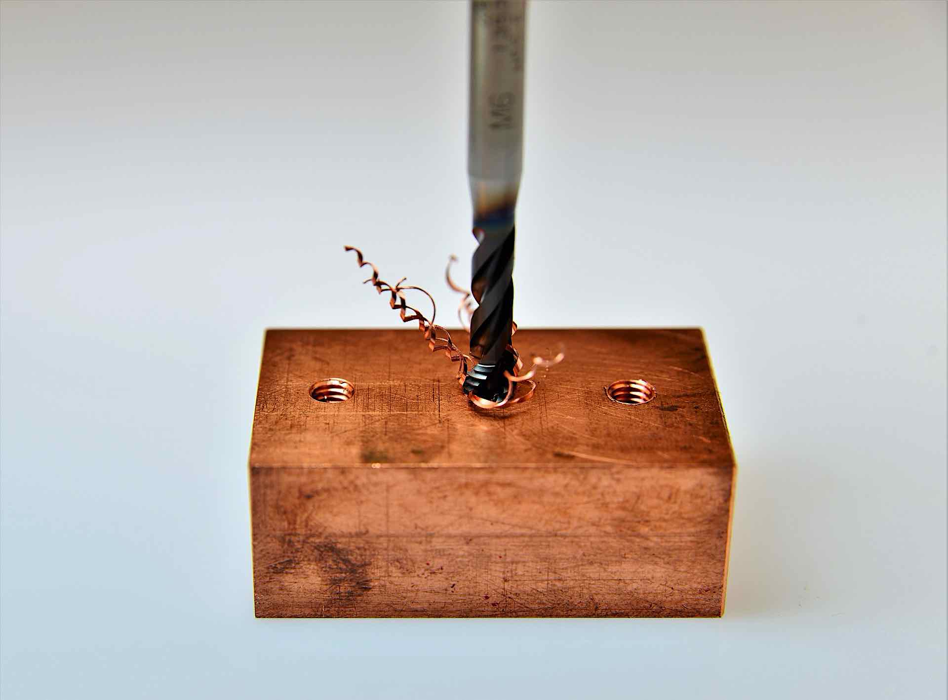
Copper alloys can be processed using various techniques. CNC milling is an automated machining process that utilizes computer control to manage the movement and operation of multi-point rotary cutting tools. As the tools rotate and move across the surface of the workpiece, they slowly remove excess material to achieve the desired shape and size. Milling can be used to create different design features such as grooves, slots, pockets, holes, slots, profiles and flats.

Here are some guidelines for CNC milling of copper or copper alloys:
►Common cutting materials are carbide application groups such as N10 and N20, and HSS grades
►You can reduce the cutting speed by 10%, which increases tool life
►When milling copper cast alloys with cast skins, reduce cutting speed by 15% for carbide group tools and 20% for HSS grade tools
CNC turning
Another technique for machining copper is CNC turning, where the tool remains stationary while the workpiece moves to create the desired shape. CNC turning is a machining system suitable for the manufacture of many electronic and mechanical parts.
There are many benefits to using CNC turning, including cost-effectiveness, precision, and increased manufacturing speed. Careful consideration of speed is especially important when turning copper workpieces, because copper is an excellent conductor of heat and generates more heat than other materials, which can increase tool wear over time.
Here are some tips for CNC turning copper or copper alloys:
►Set the tool edge angle in the range of 70° to 95°
►Softer coppers that are easily smeared require about 90° bezel
►Constant depth of cut and reduced tool edge angle reduce stress on the tool, increasing tool life and cutting speed
►Increasing the angle between the major and minor cutting edges (tool included angle) allows the tool to withstand higher mechanical loads and results in lower thermal stress
Design Considerations
There are a number of factors to consider when designing with copper machined parts. In general, you should only use copper when necessary, as copper is expensive, and it is often not necessary to produce an entire part from copper. A good design utilizes a small fraction of copper to maximize its unusual properties.

Here are some common reasons for choosing copper or copper alloy parts:
►High corrosion resistance
►High electrical and thermal conductivity for easy soldering
►High ductility
►Highly machinable alloy
Selecting the correct grade of copper for your application is very important during the design phase. For example, using pure copper for fully mechanical parts is not only difficult but also uneconomical. C101 (pure copper) is more conductive due to its purity (99.99% copper) but less machinable, while C110 is generally easier to process and therefore more cost effective. Therefore, selecting the correct material grade depends on the properties that are critical to the design's functionality.
design for manufacturability
No matter what material you use, DFM should always come first. At Fictiv, we recommend that you keep tolerances as wide as possible while retaining the functionality your application requires. Also, it is best to limit dimensional inspections, avoid deep pockets with small radii, and limit the number of part setups.
No matter what material you use, DFM should always be your first choice. We recommend that you keep the tolerances as wide as possible while retaining the functionality required by your application. Also, it is best to limit dimensional inspections, avoid deep grooves with small radii, and limit the number of part setups.
In particular, here are some specific best practices when designing copper parts:
►Maintain a minimum wall thickness of 0.5 mm
►The maximum part size for CNC milling is 1200*500*152mm, and the maximum part size for CNC turning is 152*394mm
►For undercuts, keep a square profile, full radius or dovetail profile
Finished Copper
After machining is complete, there are a number of factors to consider when deciding which process is best for your needs. The first step in surface finish control is during the CNC machining process. Certain CNC machining parameters can be controlled to alter the surface quality of the machined part, for example, the nose radius or the tool corner radius.

For soft copper alloys and pure copper, the quality of the finish depends directly and heavily on the nose radius. The nose radius should be minimized to prevent the application of softer metals and to reduce surface roughness. Doing so creates a higher quality cut surface because the smaller nose radius reduces feed marks. Compared to traditional nose radius tools, wiper inserts are the tool of choice because they can improve surface finish without changing the feed rate.
You can also achieve part finish requirements with post-processing:
►Manual polishing - although labor-intensive, polishing produces an attractive finish
►Media Sandblasting - This creates an even matte finish and hides small imperfections.
►Electropolishing - Excellent for finishing copper due to its incredible conductivity, brightens copper.
---------------------------------------------------------------------------------------------------END-----------------------------------------------------------------------------------

